Stuck open/short fault model
Digital IC design and vlsi notes
Stuck open/short fault model
- Source this playlist on Testing.
Introduction
- used at the circuit level
- each transistor can have one of three states
- working properly
- stuck open (always cutoff)
- stuck short (always on)
- When a transistor is stuck open this doesn’t mean that there is an open circuit on the finished chip,
- it can mean that some defect has caused the threshold voltage of the transistor to rise to an extent that the transistor never turns on
- or it could be an open circuit
- or a misalignment that failed to create a transistor
- When a transistor is stuck short this doesn’t mean that there is a short circuit created using metal lines,
- it can mean that the gate is always connected to supply somehow,
- it can mean that the threshold voltage of the transistor is pushed too low by some kind of accidental implant
- This is just a model used to model defects, and it shouldn’t reflect any information about the specific defect that has happen
Model
- The number of faulty states per transistor is 2
K=2
- In a circuit with
N transistor we have N*K possible faults
- assume a single fault model, single fault at a time, only a single transistor can be faulty
Example
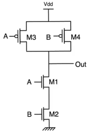
- Two input NAND gate
- first two columns represent the normal operation truth table
- when
A and B are one, the output is zero otherwise it’s Vdd
fault M2sO
- transistor M2 is stuck open
- rows of the truth table that uncovers this fault has to be rows where M2 supposed to be ON
- inputs
00 and 10 are inputs where M2 cutoff anyway so they will always produce outputs that match the correct output of the gate
- even
01 will produce correct output, because even though M2 supposed to be ON, M1 is supposed to be off cutting the path for the output to the ground anyway
- The only input combination that actually exposes this fault is
11 cause in this case there supposed to be a path to ground open by transistors M1 and M2, and M2 is stuck open so it won’t turn on
- In this case there is no path to supply or ground cause M3 and M4 are working properly cutoff so the output node is at the high impedance state
- for
M2sO the wrong output (high impedance node) and the correct output is zero
- The high impedance node could be at zero volt depending on the history of how this gate was used
- This fault can’t be uncovered by applying only this input, you have to apply atleast two inputs in sequence to uncover it
- you have to apply any input to ensure the output goes to
Vdd 00, 01, 10 then apply the faulty input 11
- if the output is still
Vdd then we know that the fault has occured
- So discovering that a node is at high impedance requires applying two inputs in sequence
fault M1sS
- transistor M1 stuck short, it’s always on
- transistor M1 will turn on if the inputs are
11 or 10 so these inputs won’t expose the fault
- input
00 also won’t produce an error cause transistor M2 will cut the way to ground
- input
01 will expose the error, because transistor M1 stuck short will provide a path to ground
- same applies to
M2sS, the only input that exposes the problem is 10
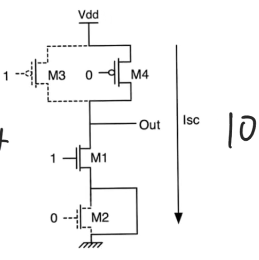
M2sS will cause a short circuit from the supply to ground in the cmos circuit,- this should never occur in the steady state for any static cmos circuit cause we should only observe either a path to ground or a path to supply
- this fault can be measured by measuring the current that’s being drawn from the supply
- if you managed to read a steady state current being drawn from the supply then that means this is an error that indicates a fault
- because in the steady state you should only observe a leakage current in the steady state