Automatic test pattern generation
Digital IC design and vlsi notes
Automatic test pattern generation
- Source this playlist on Testing.
Built-in self test
- We have considered a testing setup inwhich the chip is mounted on a testing platform, the test is applied and analysis is done offline
- Now we consider a setup where the test is performed within the chip itself this a concept called Built in self testing (BIST)
- one of the most well known forms of BIST is Power on self test (POST)
- Which happens when a chip upon powering on, runs a self test with itself and then generates reports of the results of the test
- This most often appears on complicated chips such as SOC (system-on-chip) or large microprocessors
- They are capable of running diagnostics on their own, detecting problems and identify and solve the problems sometimes
BIST setup
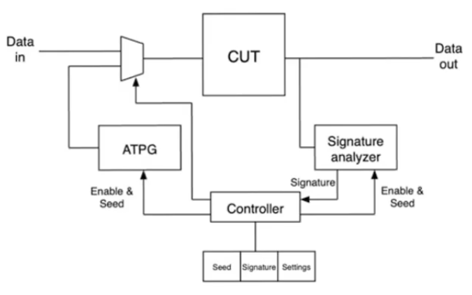
- Everything happens within the chip
- CUT: circuit under test, the non-DFT part of the chip
- The inputs to the CUT is multiplexed between
- data inputs (could be coming from ouside pins or another part of the chip)
- test input comes from another component called ATPG
- ATPG: Automatic test pattern generation
- it’s a concept indenpended of BIST, meaning that BIST doesn’t have to use ATPG but it often does
- ATPG is a way of generating test vector on the fly so that they can be applied on a test
- When the test signal is active, the input to the CUT is from the ATPG, and its output is given to a signature analyzer
- Signature analyzer takes the outputs and automatically checks if the outputs fit with the correct outputs or not
- Additionally when it detects a problem, there is a mismatch between the observed output and the correct output, it generates something called a signautre
- Signature: it’s a compressed binary word that is a representation of the problem detected on the chip
Automatic test pattern generation
- As discussed in fault coverage it’s hard to cover 100% of the possible inputs so we cover a percentage of them which leads to high fault coverage
- Testing inputs in order (000 to 111) will result in missing some intersting cases for the MSB
- so an orderly application of tests is not the kind of application that gives the faulte coverage needed
- we should apply tests that combine the input bits in a random fashion so that it exposes as many faults as possible
- on the other hand the pattern applied cannot be truly random because we need to know the pattern to generate the gold standard against to compare the output
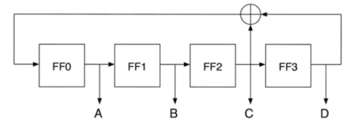
- The sequence is pseudo-random noise (PN) sequence which is generated using linear feedback shift register (LSFR)
Circuit example
- setup a seed in the shift register
1000
- The outputs of the shift register are gonna be fed as inputs to the CLB (combinational block)
- After applying clock signal, the outputs of the register are gonna shift one bit to the right except the first one will be the XOR of the two last outputs
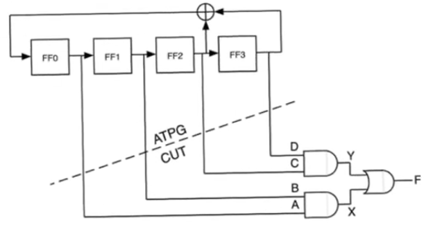
- After 15 cycles the pattern will be repeated
- the pattern of the LFSR is periodic and if it’s a well designed LFSR then the period will be
2^m - 1 cycles
- the pattern itself is well known, it can be concluded by knowing the initial pattern and the number of applied clock signal
- on the other hand if you compare the contents of the shift register from on cycle to the other the kind of shifting happening is random
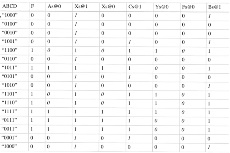
- The longer the shift register the more random it becomes, if you look at the truth table without knowing the seed the output will probably look like noise
Built In Self Tests
- if we have
m inputs, then we need to apply 2^m input pattern to the circuit to test it
- so we need to observe a stream of
F which is 2^m bits long
- With good fault coverage we don’t need to observe the entire sequence
2^m bits coming out of the CLB, instead we observe a set T which is T <= 2^m
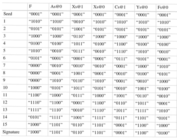
- In the example the last fault to be uncovered is the fault
Ys@0 which is uncovered after applying 8 test vectors
- This stream
F 2^m bits long needs to be compared with the gold model which is the same length
- usually comparison is made using subtractors, but for a
16 bit example we will need 2^16=64000 bit subtractor
- This will result in a huge delay, because at best the adders delay is increased logarithmically with the input bits
- This is not practical
- So we need to find a way to observe the output sequence and compress it into a smaller word that tells us the circuit if functioning proberly or not, this is exactly what happens with signature analyser
Signature analyzer
- Looks like LFSR but with some differences
- The signature analyzer does have an external input (the output of the CUT)
- We could have linear operations (XORs) between the registers of the shift register (so this can’t be described as exactly a LFSR)
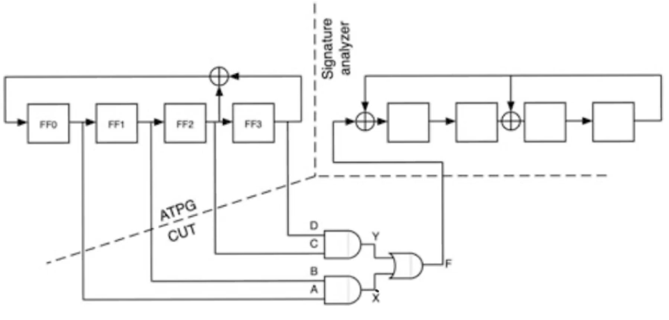
- We are gonna apply a number of cycles and at the end what remains in the shift register is called the signature
- The end is the 16th cycle in this example
- the column
F contains the content of the signature analyzer shift register
- The contents begins with a seed inserted by the user
- with the application of cycles, there is an output
F sequence coming out of the CUT
- This sequence is then fed into the analyzer with the initial seed and apply cycles
- and you keep following with the output
F applied at every cycle
- and at the end what you have remaining in the register is called the signature
- in the example it should be
1000 if the circuit is functioning properly
- You have taken a sequence of
2^m and compressed it into the remainder in the signature analyzer n bits n < 2^m
- The fact that we have compressed the output means that we can’t exactly distinguish all the faults that can occur
- The signature resulted in the analyzer might be identical for some faults
- The design of signature analyzer isn’t an easy task, you need to choose the size of the signature analyzer so that:
- It gives you a brief number (signature) that indicates whether the circuit is functioning properly or not and what kind of fault has occurred
- also because it’s a compressed signature it’ll give you false information sometimes so you don’t want that to happen very often


