Stuck at fault model
Digital IC design and vlsi notes
Stuck at fault model
- Source this playlist on Testing.
Introduction
- Fault model applied at the logic level
- Allows us to design test vectors
- Allows us to determine wether the test pattern is sufficient to detect all the possible faults
- Allows us to project fault coverage statistics
Model
- It looks at every single node of the circuit and says that said node could have three state
- normal
- stuck at logic zero
- stuck at logic one
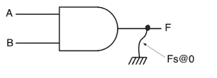
- In the example node
F is stuck at logic zero

- When we say that a node in a logic circuit is stuck at zero or one we aren’t actually implying anything about the underlying defect that caused the fault
- node
F stuck at zero doesn’t mean that F is shorted to ground
- It’s just a way to represent defects, and it could represent alot of defects, and it doesn’t imply anything about actual connections that happen in the finished chips
Example
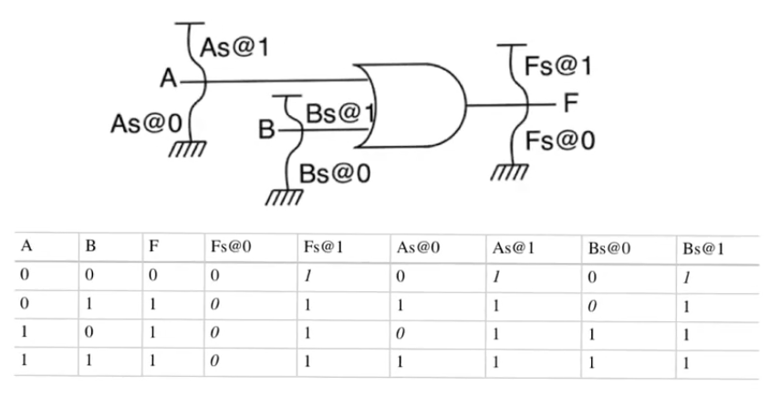
- OR gate with 2 inputs and 1 output, It has
N=3 nodes
- Number of faults that can occur =
K*N where K is the number of faults that can occur at every node
- In stuck at fault model we have 2 faults per node
K=2
- six possible faults that can occur for this circuit
- We will assume that there is only one stuck-at fault happening
- depends on the fact that the probability of a single fault occuring is much higher than the probability of multiple faults happen
- The table contains the normal output, and the output when each of the faults occur
- This table allows us to see which inputs can be used to detect which faults
- This can be done be comparing each of the columns of the table with the correct output of the circuit
- Applying inputs
A=0,B=0 isn’t useful in trying to identify the presence of F stuck at zero because the correct output matches the output when stuck
- on the other hand applying any of the other three inputs of the truth table is gonna expose
F stuck at zero because the output deviates from the true output in all three cases
- This is called an error because it’s an observation that deviates from the true output and it exposes an underlying fault
A stuck at zero will only be exposed when applying the inputs A=1,B=0- It’s useful to look at the minimum set of test vectors which can expose all the possible faults that can occur in the circuit
- This is not necessarily the entirety of the truth table
- When we try to get the minimum set that exposes all the faults we start by faults that are uncovered by only a single test
F fault at one then we start to move to faults that are uncovered by more
- In the example test vector
T={00,10,01} we don’t need to apply input 11 because the only fault exposed by applying input 11 is F stuck at zero which is also exposed by applying {01,10}
- Distinguishing which fault occured through the test vector is possible in some cases and isn’t possible in others
- If we applied test vector
01 and a fault occured this can be due to F stuck at zero or B stuck at one, this can be known by applying test 10 if a fault happens then it’s F stuck at zero, if no fault happens then it’s B stuck at one
- Faults
F, A, B stuck at one have the same observation so they can’t be distinguished if a fault happens


